 Principles of High-Performance Sealing: A Monograph on Teflon-Encapsulated O-Rings in Corrosive Vacuum Systems
1. Introduction to Encapsulated Sealing Architectures
The engineering challenge of creating a reliable, hermetic seal in environments that are simultaneously chemically aggressive and under high vacuum is one of the most persistent difficulties in tribology and fluid containment. Traditional sealing methodologies often present a binary choice that necessitates compromise: elastomeric seals (such as Nitrile, EPDM, or FKM) offer excellent resilience and “memory”—the ability to recover from deformation and maintain contact stress against flange faces—but suffer from chemical degradation, swelling, and outgassing. Conversely, solid fluoropolymer seals (such as PTFE) provide near-universal chemical inertness and low outgassing rates but lack the necessary elasticity to maintain a seal under thermal cycling or mechanical relaxation, a phenomenon known as “cold flow.”
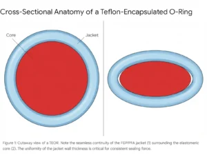
The Teflon-Encapsulated O-Ring (TEOR) represents a composite engineering solution designed to bridge this gap. By coupling the chemical impermeability of a fluoropolymer jacket (typically FEP or PFA) with the mechanical energy storage of an elastomeric core (FKM or Silicone), the TEOR creates a system that theoretically offers the “best of both worlds.” However, the successful application of this technology, particularly in the unforgiving regime of high vacuum, requires a nuanced understanding of composite mechanics, permeation thermodynamics, and material science that goes far beyond standard O-ring selection charts.
This report provides an exhaustive investigation into the best use practices for utilizing Teflon-encapsulated O-rings in corrosive vacuum applications. It synthesizes current research, manufacturer technical data, and tribological principles to offer a definitive guide on wall thickness optimization, core material selection, durometer implications, and application-specific design protocols.
2. Materials Science of the Composite System
To engineer a robust vacuum seal using TEORs, one must first deconstruct the device into its constituent materials and understand their individual and synergistic behaviors under stress and chemical exposure. The seal is not a single material but a mechanical system where the jacket acts as the chemical shield and the core acts as the spring.
2.1 The Fluoropolymer Jacket: FEP vs. PFA
The outer sheath is the primary barrier against the external environment. Unlike solid PTFE O-rings, which are machined or sintered, the jackets of encapsulated O-rings are typically extruded from melt-processable fluoropolymers. This distinction is critical because melt-processing allows for the creation of a seamless, non-porous layer that is essential for vacuum integrity. The two dominant materials are Fluorinated Ethylene Propylene (FEP) and Perfluoroalkoxy Alkane (PFA).
Fluorinated Ethylene Propylene (FEP): FEP is a copolymer of hexafluoropropylene and tetrafluoroethylene. It shares the non-stick and chemically inert properties of PTFE but has a lower melting point, which facilitates the extrusion of the thin encapsulation layer.
- Thermal Capabilities: FEP is generally rated for continuous service up to 205°C (400°F). Above this threshold, the material significantly softens, losing the hoop strength required to contain the elastomer core, leading to jacket failure or permanent deformation.
- Mechanical Compliance: A critical advantage of FEP in vacuum applications is its relatively lower flexural modulus compared to PFA. This subtle difference in stiffness allows FEP jackets to conform more readily to microscopic surface irregularities on the mating flange. In vacuum sealing, where the gas leakage path is defined by the surface roughness interface, this conformability can result in lower helium leak rates for a given clamping force.
- Friction and Wear: FEP exhibits an extremely low coefficient of friction (0.1 to 0.2), which minimizes stick-slip behavior in dynamic installation or slow-moving actuation.
Perfluoroalkoxy Alkane (PFA): PFA is a copolymer of tetrafluoroethylene and perfluoroethers. It was developed to extend the continuous service temperature of melt-processable fluoropolymers.
- Thermal Capabilities: PFA extends the operational ceiling to 260°C (500°F), with short-term excursions possible up to 300°C. This makes PFA the mandatory choice for high-temperature semiconductor processes (e.g., localized heating in CVD chambers) or chemical reactors operating exothermically.
- Mechanical Robustness: PFA possesses higher tensile strength and greater resistance to stress cracking than FEP. In applications involving frequent thermal cycling, PFA demonstrates superior resistance to the fatigue caused by the expansion and contraction of the inner core. However, this increased toughness comes with higher stiffness (modulus), which requires higher linear sealing loads (clamping force) to achieve the same degree of seal tightness as an equivalent FEP ring.
Comparative Analysis for Vacuum Specification: While PFA offers superior thermal and mechanical stats, FEP is frequently the superior choice for general corrosive vacuum applications operating below 200°C. Its lower modulus allows for a tighter seal against the “hard” surfaces typical of vacuum hardware (stainless steel, glass, ceramic) without requiring excessive bolt torque that could distort flanges or crack viewports. PFA should be reserved specifically for applications exceeding 200°C or where mechanical abrasion is a concern.
2.2 The Elastomer Core: The Engine of Recovery
The core material is the “energizer” of the system. In a vacuum seal, the pressure differential forces the seal inward, but the lack of internal pressure means the seal relies entirely on its installed compression (squeeze) to maintain contact with the gland walls. The core’s ability to push back against the jacket—its “memory”—is the determining factor in the seal’s longevity.
FKM (Viton®):
- Standard Designation: Fluoroelastomer (FKM).
- Mechanical Profile: FKM provides a high modulus of elasticity and excellent resistance to compression set (permanent deformation). It is the “workhorse” core material, providing a firm, robust reaction force that ensures the FEP jacket remains pressed against the sealing faces even after stress relaxation.
- Permeation Characteristics: Crucially for vacuum, FKM has a natively low gas permeability coefficient (approximately 2.5×10⁻⁸
- torr-liters/sec/linear inch for Air, compared to significantly higher rates for other elastomers). In the event of slow permeation through the FEP jacket, the FKM core acts as a substantial secondary barrier, retarding the ingress of atmospheric gases into the vacuum chamber.
- Temperature Range: Typically -15°C to +200°C. Its limitation is low-temperature flexibility; below -20°C, FKM becomes glassy and loses its sealing force, which can be catastrophic if the vacuum system is subjected to cryogenic cycles or outdoor conditions.
Silicone (VMQ):
- Standard Designation: Silicone Rubber (VMQ).
- Mechanical Profile: Silicone is significantly softer and more elastic than FKM. It has a faster recovery rate, meaning it springs back almost instantly after deformation. This “snappiness” allows Silicone-core TEORs to maintain contact during rapid thermal transients or vibration.
- Permeation Characteristics: The major drawback of silicone in vacuum applications is its extremely high gas permeability—often 10 to 100 times greater than FKM. If the FEP jacket allows permeation (which it does, albeit slowly), the silicone core offers negligible resistance to the gas flow. It effectively acts as a porous medium for gas transport once the barrier layer is passed.
- Temperature Range: Silicone excels in extreme temperature bandwidths, remaining flexible down to -60°C and stable up to +260°C. This makes it the only viable core option for cryogenic vacuum lines (e.g., liquid nitrogen feeds) or extremely high-temperature PFA-jacketed seals where FKM would degrade.
Design Verdict: For Ultra-High Vacuum (UHV) and High Vacuum (HV) applications where ultimate pressure and leak rate are the primary metrics, FEP-encapsulated FKM is the preferred configuration due to the “series resistance” to permeation provided by the FKM core. Silicone cores should be restricted to cryogenic applications, low-closing-force requirements, or systems where the vacuum requirements are modest (rough vacuum) but temperature extremes are severe.
3. Core Geometry and Durometer: Fine-Tuning Seal Mechanics
Beyond the chemical composition, the geometric and hardness properties of the core fundamentally alter the seal’s behavior. The selection of solid versus hollow cores and the specific durometer of the elastomer allows the engineer to “tune” the seal to the available clamping force and flange fragility.
3.1 Solid Core vs. Hollow Core
Solid Core: The solid core is the industry standard for the majority of static flange seals.
- Mechanics: It provides the maximum resistance to compression. This high reaction force is beneficial for maintaining a seal under high internal pressures or in robust stainless steel vacuum flanges (e.g., ISO-K, CF, or ASA flanges) where the bolts can withstand significant torque.
- Vacuum Stability: Solid cores are inherently stable in vacuum. They contain no internal voids that can become pressurized traps for gas.
Hollow Core: Hollow core TEORs feature a tubular elastomer core (usually silicone) encapsulated in the fluoropolymer jacket.
- Compliance Advantage: The primary engineering justification for a hollow core is the drastic reduction in linear closing force required to achieve a seal. A hollow core can be compressed to the requisite 20% squeeze with significantly less load than a solid core.
- Applications: This characteristic is indispensable for sealing fragile components such as:
- Glass or quartz viewports.
- Ceramic insulators.
- Plastic or graphite flanges.
- Large, rectangular doors on vacuum vessels (e.g., Lyophilizers) where the latching mechanism cannot generate the tons of force required to compress a solid rope seal 20-30 feet long.
- The Vacuum Collapse Risk: The physics of hollow cores in vacuum presents a unique paradox.
- External Vacuum: When the chamber is evacuated, the pressure outside the O-ring drops. If the hollow core is sealed at 1 atmosphere, the pressure inside the core is now higher than the outside. The core attempts to expand (“balloon”), which actually increases the contact pressure against the sealing faces. In this static state, a hollow core performs well.
- The “Virtual Leak” Trap: If the seal remains in vacuum for extended periods (weeks or months), gas from inside the hollow core may slowly permeate out through the jacket or the splice, eventually equilibrating with the vacuum. When the chamber is vented back to atmosphere, the core is now at low pressure while the outside is at 1 atm. The core effectively implodes or collapses. If the door is immediately opened and re-closed, the seal may be flat and lifeless, failing to seal until air permeates back in (a very slow process).
- Venting: To prevent bursting during high-temperature/high-pressure cycling, some manufacturers offer “vented” hollow cores with laser-drilled holes. However, venting is catastrophic for vacuum applications. A vented hollow core creates a massive volume of trapped gas connected to the vacuum space, acting as a perpetual virtual leak that will make reaching high vacuum impossible.
- Recommendation: Hollow core TEORs for vacuum service must be non-vented and are best used for rough vacuum or short-cycle applications. For UHV, solid cores are safer to avoid the physics of trapped volumes.
3.2 Durometer and “Apparent Hardness”
In standard rubber O-rings, durometer (Shore A hardness) directly correlates to stiffness. In TEORs, the relationship is decoupled due to the jacket.
The “Apparent Hardness” Phenomenon: When a durometer gauge is pressed against an encapsulated O-ring, it is primarily measuring the resistance of the stiff FEP/PFA jacket, not the soft core underneath.
- Standard Reading: Most encapsulated O-rings will register an “apparent” hardness of 85-95 Shore A, regardless of whether the core is 70 Shore A Silicone or 90 Shore A FKM.
- Implication: Engineers cannot rely on durometer specifications to predict the “feel” or compliance of the ring. A “75 Durometer” spec on a TEOR datasheet usually refers to the core hardness, but the installed behavior will be that of a much harder seal (closer to 90 durometer).
- Design Consequence: Because the system behaves like a hard (90 durometer) seal, it requires:
- Better Surface Finish: Hard seals do not flow into surface scratches.
- Higher Load: More force per linear inch to achieve the same contact patch area.
Table 1: Modeling Core vs. Apparent Hardness
| Jacket Type | Core Material | Core Hardness (Shore A) | Apparent System Hardness | Application Focus |
| Low-Modulus PFA | Silicone | 60 | ~80 ShA | Fragile Flanges, Low Load |
| Standard FEP | FKM (Viton) | 70-75 | ~90-92 ShA | Standard Vacuum Hardware |
| High-Modulus PFA | FKM (Viton) | 90 | ~98 ShA | Extreme Pressure, No-Stretch |
Export to Sheets
Data synthesized from.
4. Wall Thickness: The Critical Trade-Off
The thickness of the encapsulation jacket is a parameter often overlooked but vital for vacuum performance. Manufacturers typically offer “Standard” and “Thick” (or Heavy Duty) wall options.
4.1 Thinner Jacket Encapsulation
- Mechanics: A thinner jacket (e.g., 0.010″ – 0.015″) imposes less structural stiffness on the assembly. This allows the core’s elasticity to dominate, improving the seal’s ability to conform to groove irregularities.
- Vacuum Performance: Thin jackets are preferred for sealing against glass, quartz, or ceramic surfaces. The reduced stiffness minimizes the point-loading that leads to stress fractures in brittle mating materials.
- Risk: Thin jackets are more susceptible to installation damage (kinking) and offer a shorter diffusion path for permeation.
4.2 Thicker Jacket Encapsulation
- Mechanics: Thicker jackets significantly increase the seal’s modulus.
- Permeation Resistance: In vacuum applications, permeation follows Fick’s laws of diffusion, where flux is inversely proportional to thickness (J=−D
- dx
- dc
-
- ). A thicker jacket increases the diffusion path length (dx), theoretically reducing the permeation rate of atmospheric gases into the vacuum chamber.
- Chemical Durability: A thicker wall provides a greater buffer against chemical attack, swelling, or plasma erosion before the core is breached.
- Compression Set Risk: The downside is increased compression set. Because the fluoropolymer does not recover as well as the elastomer, a thicker jacket means a larger portion of the seal’s cross-section is susceptible to permanent deformation (cold flow). Over time, a thick-jacketed seal may “flatten out” more than a thin-jacketed one, potentially leaking if the flange relaxes.
Best Practice: For metal UHV systems, specify Standard to Thick walls to minimize permeation, provided adequate clamping force is available. For glass/quartz or low-force systems, Thin walls are mandatory to ensure seal integrity without hardware damage.
5. Vacuum Physics: Permeation and Virtual Leaks
Sealing a vacuum system with TEORs presents challenges fundamentally different from liquid handling. The two primary enemies of high vacuum are Permeation and Virtual Leaks.
5.1 Permeation Thermodynamics
Permeation is the bulk transport of gas through the seal material. TEORs present a complex permeation pathway. The FEP/PFA jacket is generally a superior barrier to atmospheric gases (N2O2) compared to most elastomers, but it is not impermeable.
- Helium Transparency: Fluoropolymers can be relatively permeable to Helium. This is critical during leak checking; a TEOR may show a “ghost” leak response where Helium diffuses through the seal during the test, mimicking a real leak.
- Moisture Barrier: FEP is an exceptional barrier to water vapor (H2O), which is often the dominant gas load in vacuum systems. This makes TEORs excellent for systems requiring fast pump-down times, as they do not act as “water sponges” like generic Nylon or untreated Nitrile seals.
5.2 The Virtual Leak Phenomenon
A virtual leak occurs when a volume of gas trapped inside the vacuum chamber (but not part of the process environment) slowly leaks out through a restriction.
- The Interface Trap: In a TEOR, the interface between the core and the jacket is a potential trap. If the seal is manufactured with air gaps, or if air permeates into this space during atmospheric storage, it creates a pressurized pocket. Under vacuum, this gas slowly diffuses out through the jacket or the splice.
- Impact: This results in a system that pumps down to a certain level (e.g., 10−4 Torr) and then stalls, behaving exactly like a real leak.
- Prevention: This underscores the necessity of sourcing high-quality TEORs where the core is sized to completely fill the jacket without voids. It also reinforces the recommendation against vented hollow cores in vacuum.
6. Installation and Groove Design: The “Zero-Leak” Protocol
The unforgiving nature of the FEP/PFA jacket means that standard O-ring groove designs (AS568) often require modification to ensure a vacuum-tight seal.
6.1 Surface Finish Requirements
This is the single most common cause of failure in vacuum TEOR installations. A soft rubber O-ring flows into surface imperfections, sealing scratches up to 64 µin Ra. A TEOR does not.
- Liquid Service: Standard 32 µin Ra (0.8 µm) is acceptable.
- Vacuum Service: The surface must be significantly smoother. 16 µin Ra (0.4 µm) or better is required.
- The Physics: The harder FEP jacket bridges over microscopic valleys in a rough finish rather than filling them. In a vacuum, gas molecules can travel along these spiral leak paths. Polished surfaces are mandatory.
6.2 Groove Geometry and Compression
- Compression (Squeeze): Target 20-25%. Less than 15% may leak due to insufficient contact stress; more than 30% risks cracking the jacket or causing permanent set.
- Fill Factor: Do not exceed 85-90% fill. FEP has a high coefficient of thermal expansion (CTE). If the groove is too full, thermal expansion during bake-out will have nowhere to go but to extrude the jacket, rupturing the seal.
- Corner Radii: Grooves must have generous radii. Sharp corners can cut the jacket during installation or under pressure.
6.3 Installation Protocol
Installation damage is a primary failure mode.
- Heating: It is standard practice to heat TEORs in hot water (approx. 100°C) or an oven before installation. This softens the jacket, reducing the modulus and the risk of kinking or cracking during stretching.
- No-Roll Rule: Unlike rubber O-rings, which can be rolled down a shaft, rolling a TEOR will kink the jacket. Rolling twists the non-bonded jacket relative to the core, creating permanent wrinkles. A wrinkle acts as a capillary tube leak path. Always stretch and slide; never roll.
- Stretch Limit: Do not stretch more than 8-10% during installation. Excessive stretch yields the FEP jacket (it turns white/opaque), permanently ruining the seal.
7. Application Case Studies
7.1 Pharmaceutical Lyophilization (Freeze Drying)
- Application: Sealing the main chamber door and condenser ports.
- Conditions: High vacuum, low temperature (-40°C to -50°C), followed by Steam-In-Place (SIP) sterilization at 121°C and Clean-In-Place (CIP) with aggressive alkaline detergents.
- Best Practice: Hollow Silicone Core / FEP Jacket.
- Logic: The silicone core is essential for the -50°C freezing cycle where FKM would become brittle and leak. The FEP jacket protects the silicone from the harsh CIP chemicals and steam that would otherwise degrade it. The hollow core is frequently used because large rectangular lyophilizer doors often have latching mechanisms with limited closing force, and a solid seal would require tons of force to compress.
7.2 Semiconductor Etch (Chlorine/Bromine Chemistries)
- Application: Gas delivery lines and exhaust abatement for Cl2, HBr, and BCl3.
- Conditions: Corrosive gases, medium vacuum, moderate temperatures.
- Best Practice: Solid FKM Core / FEP Jacket.
- Logic: FEP is inert to halogens at standard temperatures. The solid FKM core provides the necessary permeation resistance to prevent toxic gas release into the cleanroom (safety) and atmospheric ingress into the line (process purity).
- Plasma Warning: If the seal is exposed to direct plasma, FEP will erode (“ash”). In direct plasma regions, a solid Perfluoroelastomer (FFKM) is superior. TEORs are suitable for downstream or upstream locations protected from ion bombardment.
7.3 Chemical Processing (Reactors & Pumps)
- Application: Flange seals on reactor vessels handling aggressive solvents (THF, MEK) or acids.
- Conditions: Positive pressure to rough vacuum, potential for high temperatures.
- Best Practice: Solid FKM Core / PFA Jacket.
- Logic: PFA is chosen if temperatures exceed 200°C. Solid FKM provides the robust blowout resistance required for pressure cycling.
8. Failure Modes and Troubleshooting
| Symptom | Probable Cause | Mechanism | Corrective Action |
| Flat spots on ID/OD | Compression Set | Jacket cold flow due to excessive heat or load. | Switch to PFA jacket; reduce clamping force; check temp limits. |
| Blisters / Bubbles | Explosive Decompression | Gas trapped between core/jacket expanded rapidly. | Slow down venting rate; switch to solid homogeneous seal if RGD is frequent. |
| Cracked Jacket | Embrittlement or Over-stress | Chemical attack (e.g., Fluorine) or installation stretch >10%. | Check chemical compatibility (F2?); review installation procedure. |
| “Baggy” Jacket | Solvent Swelling | Core swelled due to permeation, stretching jacket, then shrunk. | Check if core material is compatible with permeating gas (e.g., use FKM core for fuels). |
| White Stress Marks | Yielding | Cold installation or excessive stretch. | Use hot water install method; ensure stretch <8%. |
9. Conclusion
The Teflon-Encapsulated O-ring is a sophisticated composite device that serves as a critical enabler for modern high-purity and corrosive vacuum processes. It allows engineers to bypass the limitations of standard elastomers without incurring the extreme costs of FFKM (Perfluoroelastomer) seals in every location. However, its success is contingent upon respecting its mechanical limitations: it is stiffer, less elastic, and more sensitive to surface finish than the rubber seals it replaces.
By selecting the appropriate core material (FKM for vacuum/permeation, Silicone for cold/compliance), optimizing wall thickness for the specific hardware, and adhering to strict installation protocols, scientists and engineers can achieve reliable, long-term vacuum integrity in the most demanding chemical environments.