SS Helical Encapsulated Springs
FEP/PFA-jacketed, stainless ribbon-spring energized seals for cryogenic, corrosive, and high-purity service.
M-Cor’s SS Helical Encapsulated Springs combine a stainless steel flat-wound ribbon energizer with a clear FEP or PFA fluoropolymer jacket. The jacket helps isolate the metal spring from the process media, while the spring provides elastic preload.
Request Engineering Review View Encapsulated O-Rings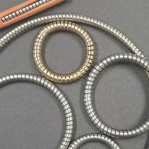
What It Is
SS Helical Encapsulated Springs are part of M-Cor’s encapsulated O-ring product line. They are designed for applications where chemical resistance, spring force, metal isolation, and clean sealing behavior are required.
Fluoropolymer Jacket
FEP or PFA jacket surrounds the spring and helps resist chemical attack.
Stainless Ribbon Spring
Flat-wound stainless spring provides preload and sealing force.
Specialty Service
Useful for cryogenic, corrosive, high-purity, and axial face-seal applications.
Where ESS Series Seals Excel
Cryogenic Systems
Stable elastic preload at deep-cold temperatures. Jackets can be micro-vented when required.
Aggressive Chemistries
FEP/PFA exterior resists many chemicals and provides a smooth, cleanable surface.
High-Purity Assemblies
The jacket separates metal from the media and helps reduce contamination risk.
Why Vent Holes May Be Required
For cryogenic or higher-pressure applications, small vent holes can be specified in the FEP/PFA jacket. These vents help equalize pressure and reduce the risk of jacket damage during thermal or pressure cycling.
Engineering note: For cryogenic service or applications above approximately 1500 psi, specify a vented jacket for review.
Temperature, Spring, and Installation Notes
FEP Jacket
Approx. −250°C to +204°C
(−420°F to +428°F)
PFA Jacket
Approx. −250°C to +260°C
(−420°F to +500°F)
Spring Standard
Flat-wound ribbon compression spring. 302 stainless is standard. 316L or 17-7PH available.
- Avoid excessive stretch during installation.
- Best suited for axial or face-seal geometries.
- Specify vented jackets for cryogenic service, rapid cycling, or high-pressure applications.
M-Cor ESS Engineering Guide by Cross-Section
The values below are guidance for encapsulated flat-wound helical spring O-rings with FEP/PFA jackets. Always verify against groove design, squeeze target, media, pressure, and temperature.
1.91 mm (0.075 in)
Squeeze: 0.56 mm (0.022 in)
Groove Depth: 1.35 mm (0.053 in)
Groove Width: 2.67 mm (0.105 in)
Minimum ID: 12.70 mm (0.500 in)
Force: 40 lb/in
2.40 mm (0.094 in)
Squeeze: 0.61 mm (0.024 in)
Groove Depth: 1.78 mm (0.070 in)
Groove Width: 3.18 mm (0.125 in)
Minimum ID: 19.05 mm (0.750 in)
Force: 40 lb/in
2.62 mm (0.103 in)
Squeeze: 0.71 mm (0.028 in)
Groove Depth: 1.90 mm (0.075 in)
Groove Width: 3.53 mm (0.139 in)
Minimum ID: 19.05 mm (0.750 in)
Force: 45 lb/in
2.92 mm (0.115 in)
Squeeze: 0.76 mm (0.030 in)
Groove Depth: 2.16 mm (0.085 in)
Groove Width: 3.94 mm (0.155 in)
Minimum ID: 31.75 mm (1.250 in)
Force: 40 lb/in
3.00 mm (0.118 in)
Squeeze: 0.76 mm (0.030 in)
Groove Depth: 2.24 mm (0.088 in)
Groove Width: 3.96 mm (0.156 in)
Minimum ID: 31.75 mm (1.250 in)
Force: 45 lb/in
3.10 mm (0.122 in)
Squeeze: 0.76 mm (0.030 in)
Groove Depth: 2.34 mm (0.092 in)
Groove Width: 4.07 mm (0.160 in)
Minimum ID: 31.75 mm (1.250 in)
Force: 50 lb/in
3.53 mm (0.139 in)
Squeeze: 0.76 mm (0.030 in)
Groove Depth: 2.79 mm (0.110 in)
Groove Width: 4.95 mm (0.195 in)
Minimum ID: 31.75 mm (1.250 in)
Force: 65 lb/in
3.80 mm (0.150 in)
Squeeze: 0.84 mm (0.033 in)
Groove Depth: 2.92 mm (0.115 in)
Groove Width: 4.95 mm (0.195 in)
Minimum ID: 38.10 mm (1.500 in)
Force: 85 lb/in
4.00 mm (0.157 in)
Squeeze: 0.89 mm (0.035 in)
Groove Depth: 3.10 mm (0.122 in)
Groove Width: 5.08 mm (0.200 in)
Minimum ID: 38.10 mm (1.500 in)
Force: 70 lb/in
4.32 mm (0.170 in)
Squeeze: 1.02 mm (0.040 in)
Groove Depth: 3.30 mm (0.130 in)
Groove Width: 5.84 mm (0.230 in)
Minimum ID: 38.10 mm (1.500 in)
Force: 90 lb/in
4.50 mm (0.177 in)
Squeeze: 1.02 mm (0.040 in)
Groove Depth: 3.48 mm (0.137 in)
Groove Width: 6.02 mm (0.237 in)
Minimum ID: 38.10 mm (1.500 in)
Force: 100 lb/in
4.88 mm (0.192 in)
Squeeze: 1.12 mm (0.044 in)
Groove Depth: 3.76 mm (0.148 in)
Groove Width: 6.48 mm (0.255 in)
Minimum ID: 44.45 mm (1.750 in)
Force: 110 lb/in
5.34 mm (0.210 in)
Squeeze: 1.14 mm (0.045 in)
Groove Depth: 4.19 mm (0.165 in)
Groove Width: 7.11 mm (0.280 in)
Minimum ID: 50.80 mm (2.000 in)
Force: 140 lb/in
6.35 mm (0.250 in)
Squeeze: 1.27 mm (0.050 in)
Groove Depth: 5.08 mm (0.200 in)
Groove Width: 8.25 mm (0.325 in)
Minimum ID: 76.20 mm (3.000 in)
Force: 110 lb/in
6.99 mm (0.275 in)
Squeeze: 1.27 mm (0.050 in)
Groove Depth: 5.71 mm (0.225 in)
Groove Width: 8.89 mm (0.350 in)
Minimum ID: 88.90 mm (3.500 in)
Force: 95 lb/in
8.00 mm (0.315 in)
Squeeze: 1.52 mm (0.060 in)
Groove Depth: 6.48 mm (0.255 in)
Groove Width: 9.90 mm (0.390 in)
Minimum ID: 101.60 mm (4.000 in)
Force: 80 lb/in
Cross-Section and Minimum ID Tolerances
1.78 mm (0.070 in)
Tolerance: ±0.12 mm (0.005 in)
Minimum ID: 10.60 mm (0.417 in)
1.91 mm (0.075 in)
Tolerance: ±0.15 mm (0.006 in)
Minimum ID: 12.70 mm (0.500 in)
2.00 mm (0.079 in)
Tolerance: ±0.15 mm (0.006 in)
Minimum ID: 19.05 mm (0.750 in)
2.40 mm (0.094 in)
Tolerance: ±0.15 mm (0.006 in)
Minimum ID: 19.05 mm (0.750 in)
2.62 mm (0.103 in)
Tolerance: ±0.15 mm (0.006 in)
Minimum ID: 19.05 mm (0.750 in)
2.72 mm (0.107 in)
Tolerance: ±0.15 mm (0.006 in)
Minimum ID: 19.08 mm (0.751 in)
2.92 mm (0.115 in)
Tolerance: ±0.15 mm (0.006 in)
Minimum ID: 31.75 mm (1.250 in)
3.00 mm (0.118 in)
Tolerance: ±0.15 mm (0.006 in)
Minimum ID: 31.75 mm (1.250 in)
3.10 mm (0.122 in)
Tolerance: ±0.15 mm (0.006 in)
Minimum ID: 31.75 mm (1.250 in)
3.53 mm (0.139 in)
Tolerance: ±0.15 mm (0.006 in)
Minimum ID: 31.75 mm (1.250 in)
3.80 mm (0.150 in)
Tolerance: ±0.20 mm (0.008 in)
Minimum ID: 38.10 mm (1.500 in)
4.00 mm (0.157 in)
Tolerance: ±0.20 mm (0.008 in)
Minimum ID: 38.10 mm (1.500 in)
4.32 mm (0.170 in)
Tolerance: ±0.20 mm (0.008 in)
Minimum ID: 38.10 mm (1.500 in)
4.88 mm (0.192 in)
Tolerance: ±0.20 mm (0.008 in)
Minimum ID: 44.45 mm (1.750 in)
5.00 mm (0.197 in)
Tolerance: ±0.25 mm (0.010 in)
Minimum ID: 50.80 mm (2.000 in)
5.34 mm (0.210 in)
Tolerance: ±0.25 mm (0.010 in)
Minimum ID: 50.80 mm (2.000 in)
6.35 mm (0.250 in)
Tolerance: ±0.43 mm (0.017 in)
Minimum ID: 76.20 mm (3.000 in)
6.99 mm (0.275 in)
Tolerance: ±0.43 mm (0.017 in)
Minimum ID: 88.90 mm (3.500 in)
8.00 mm (0.315 in)
Tolerance: ±0.43 mm (0.017 in)
Minimum ID: 101.60 mm (4.000 in)
Note: Inch equivalents are simple conversions. Always validate final dimensions against the application, drawing, and quote.
Inside-Diameter Tolerance Bands
10.60–16.09 mm
Inches: 0.417–0.633 in
Tolerance: ±0.20 mm (0.008 in)
16.10–25.09 mm
Inches: 0.634–0.988 in
Tolerance: ±0.25 mm (0.010 in)
25.10–40.09 mm
Inches: 0.988–1.579 in
Tolerance: ±0.35 mm (0.014 in)
40.10–63.09 mm
Inches: 1.579–2.484 in
Tolerance: ±0.40 mm (0.016 in)
63.10–100.09 mm
Inches: 2.484–3.941 in
Tolerance: ±0.50 mm (0.020 in)
100.10–160.00 mm
Inches: 3.941–6.299 in
Tolerance: ±0.70 mm (0.028 in)
Over 160.00 mm
Inches: Over 6.299 in
Tolerance: ±0.50%
How to Specify SS Helical Encapsulated Springs
- Environment: media, pressure, steady and transient temperatures.
- Jacket: FEP for clarity and chemical resistance, or PFA for higher temperature headroom.
- Spring: 302 stainless standard; 316L or 17-7PH by requirement.
- Venting: add V for cryogenic or higher-pressure applications.
- Groove and squeeze: use the guidance above, then confirm with M-Cor.
Example part code:
ESS-C-302-PFA-CS3.53-ID50-V
Compression, 302 ribbon spring, PFA jacket, 3.53 mm cross-section, 50 mm inside diameter, vented.
Typical Applications
Cryogenic Equipment
Valves, regulators, LOX/LN₂ handling, and test stands.
Semiconductor Systems
Wet process components where metal isolation matters.
Pharma and Biotech
Cleanable, low-particle sealing applications.
Chemical and Washdown
Equipment needing corrosion-resistant force elements.
FAQ
Why use vent holes?
Vents are tiny engineered features in the jacket. They are used for cryogenic or higher-pressure service to help prevent jacket damage from pressure differentials.
How cold or hot can these run?
Referenced ranges are approximately −250°C to +204°C for FEP and up to +260°C for PFA. M-Cor confirms suitability against the actual application.
Any installation cautions?
Avoid over-stretching during installation. These seals are best used in axial or face-seal arrangements.