SS Helical Encapsulated Springs (ESS Series)
FEP/PFA-jacketed, stainless ribbon-spring energized seals for cryogenic, corrosive, and high-purity service
What it is
M-Cor’s SS Helical Encapsulated Springs (ESS Series) combines a stainless steel flat-wound (ribbon) energizer with a fluoropolymer (FEP or PFA) jacket to create a low-friction, chemically inert seal that keeps metal isolated from process media while maintaining elastic preload. This construction is the same core architecture documented for aerospace-grade encapsulated spring O-rings (ribbon spring inside FEP/PFA).
Where it excels
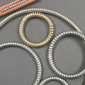
M-Cor Helical Springs in Standard AS Sizes
Cryogenic systems: stable elastic preload at deep-cold temperatures; jacket can be micro-vented to manage pressure differentials.
Aggressive chemistries / washdown: smooth FEP/PFA exterior resists chemicals and cleans easily (fluoropolymer jacket over stainless spring).
High-purity assemblies: jacket separates metal from media and minimizes particulate generation; axial/face-seal use is typical.
Why there are holes in the jacket (cryogenic & high-pressure note)
For cryogenic or higher-pressure applications, small vent holes can be specified in the FEP/PFA jacket. These vents equalize pressure and prevent jacket damage (e.g., collapse/blow-out) during thermal/pressure cycling—an industry-documented practice above roughly 1500 psi.
Temperature capability (assembly)
- FEP-jacketed springs: approximately −250 °C to +204 °C (≈ −420 °F to +428 °F).
- PFA-jacketed springs: approximately −250 °C to +260 °C (≈ −420 °F to +500 °F).
These ranges reflect widely published data for ribbon-spring encapsulated seals; M-Cor verifies selections against your media, duty cycle, and groove.
Recommended internal spring (standard)
- Type: Flat-wound ribbon compression spring (continuous coil).
- Alloy: Stainless 302 standard (AMS 5059/ASTM Type 302); 316L or 17-7PH available to suit strength/corrosion needs.
- Reason: This energizer style is the referenced, proven choice for FEP/PFA encapsulated O-rings in deep-cold and dynamic service.
Installation & use notes
- Avoid excessive stretch during install to keep the ribbon coils seated (best used in axial/face-seal geometries).
- For >~1500 psi service or rapid cryogenic cycling, specify vented jackets.
Sizes & design guidance
Industry tables show a broad span of cross-sections with associated groove dimensions and force-per-linear-inch guidance. For example, CS 3.53 mm commonly targets ~0.76 mm squeeze with representative load guidance per linear inch; minimum IDs vary by CS. (Full tables are available on request; use as guidance and finalize per application.)
Tolerances reference: Documents list typical cross-section and inside-diameter tolerance bands by size family; M-Cor aligns to the project’s specification window and will confirm on the quote/print.
| Cross Section | Squeeze | Groove Depth | Groove Width | Minimum ID | Force (lb/in) |
|---|---|---|---|---|---|
| 1.91 mm (0.075 in) | 0.56 mm (0.022 in) | 1.35 mm (0.053 in) | 2.67 mm (0.105 in) | 12.70 mm (0.500 in) | 40 |
| 2.40 mm (0.094 in) | 0.61 mm (0.024 in) | 1.78 mm (0.070 in) | 3.18 mm (0.125 in) | 19.05 mm (0.750 in) | 40 |
| 2.62 mm (0.103 in) | 0.71 mm (0.028 in) | 1.90 mm (0.075 in) | 3.53 mm (0.139 in) | 19.05 mm (0.750 in) | 45 |
| 2.92 mm (0.115 in) | 0.76 mm (0.030 in) | 2.16 mm (0.085 in) | 3.94 mm (0.155 in) | 31.75 mm (1.250 in) | 40 |
| 3.00 mm (0.118 in) | 0.76 mm (0.030 in) | 2.24 mm (0.088 in) | 3.96 mm (0.156 in) | 31.75 mm (1.250 in) | 45 |
| 3.10 mm (0.122 in) | 0.76 mm (0.030 in) | 2.34 mm (0.092 in) | 4.07 mm (0.160 in) | 31.75 mm (1.250 in) | 50 |
| 3.53 mm (0.139 in) | 0.76 mm (0.030 in) | 2.79 mm (0.110 in) | 4.95 mm (0.195 in) | 31.75 mm (1.250 in) | 65 |
| 3.80 mm (0.150 in) | 0.84 mm (0.033 in) | 2.92 mm (0.115 in) | 4.95 mm (0.195 in) | 38.10 mm (1.500 in) | 85 |
| 4.00 mm (0.157 in) | 0.89 mm (0.035 in) | 3.10 mm (0.122 in) | 5.08 mm (0.200 in) | 38.10 mm (1.500 in) | 70 |
| 4.32 mm (0.170 in) | 1.02 mm (0.040 in) | 3.30 mm (0.130 in) | 5.84 mm (0.230 in) | 38.10 mm (1.500 in) | 90 |
| 4.50 mm (0.177 in) | 1.02 mm (0.040 in) | 3.48 mm (0.137 in) | 6.02 mm (0.237 in) | 38.10 mm (1.500 in) | 100 |
| 4.88 mm (0.192 in) | 1.12 mm (0.044 in) | 3.76 mm (0.148 in) | 6.48 mm (0.255 in) | 44.45 mm (1.750 in) | 110 |
| 5.34 mm (0.210 in) | 1.14 mm (0.045 in) | 4.19 mm (0.165 in) | 7.11 mm (0.280 in) | 50.80 mm (2.000 in) | 140 |
| 6.35 mm (0.250 in) | 1.27 mm (0.050 in) | 5.08 mm (0.200 in) | 8.25 mm (0.325 in) | 76.20 mm (3.000 in) | 110 |
| 6.99 mm (0.275 in) | 1.27 mm (0.050 in) | 5.71 mm (0.225 in) | 8.89 mm (0.350 in) | 88.90 mm (3.500 in) | 95 |
| 8.00 mm (0.315 in) | 1.52 mm (0.060 in) | 6.48 mm (0.255 in) | 9.90 mm (0.390 in) | 101.60 mm (4.000 in) | 80 |
Notes: Values are guidance for encapsulated flat-wound helical spring O-rings with FEP/PFA jackets.
Verify against your groove, squeeze target, pressure/temperature, and media. For cryogenic or >~1500 psi
service, specify a vented jacket (micro-vents) to prevent jacket collapse/blow-out.
Reference: Engineering table for encapsulated helical-spring seals (cross section, squeeze,
groove depth/width, min ID, force).
| Cross Section | Tolerance ± | Minimum Inside Diameter |
|---|---|---|
| 1.78 mm (0.070 in) | 0.12 mm (0.005 in) | 10.60 mm (0.417 in) |
| 1.91 mm (0.075 in) | 0.15 mm (0.006 in) | 12.70 mm (0.500 in) |
| 2.00 mm (0.079 in) | 0.15 mm (0.006 in) | 19.05 mm (0.750 in) |
| 2.40 mm (0.094 in) | 0.15 mm (0.006 in) | 19.05 mm (0.750 in) |
| 2.62 mm (0.103 in) | 0.15 mm (0.006 in) | 19.05 mm (0.750 in) |
| 2.72 mm (0.107 in) | 0.15 mm (0.006 in) | 19.08 mm (0.751 in) |
| 2.92 mm (0.115 in) | 0.15 mm (0.006 in) | 31.75 mm (1.250 in) |
| 3.00 mm (0.118 in) | 0.15 mm (0.006 in) | 31.75 mm (1.250 in) |
| 3.10 mm (0.122 in) | 0.15 mm (0.006 in) | 31.75 mm (1.250 in) |
| 3.53 mm (0.139 in) | 0.15 mm (0.006 in) | 31.75 mm (1.250 in) |
| 3.80 mm (0.150 in) | 0.20 mm (0.008 in) | 38.10 mm (1.500 in) |
| 4.00 mm (0.157 in) | 0.20 mm (0.008 in) | 38.10 mm (1.500 in) |
| 4.32 mm (0.170 in) | 0.20 mm (0.008 in) | 38.10 mm (1.500 in) |
| 4.88 mm (0.192 in) | 0.20 mm (0.008 in) | 44.45 mm (1.750 in) |
| 5.00 mm (0.197 in) | 0.25 mm (0.010 in) | 50.80 mm (2.000 in) |
| 5.34 mm (0.210 in) | 0.25 mm (0.010 in) | 50.80 mm (2.000 in) |
| 6.35 mm (0.250 in) | 0.43 mm (0.017 in) | 76.20 mm (3.000 in) |
| 6.99 mm (0.275 in) | 0.43 mm (0.017 in) | 88.90 mm (3.500 in) |
| 8.00 mm (0.315 in) | 0.43 mm (0.017 in) | 101.60 mm (4.000 in) |
| Inside Diameter Range | Tolerance ± |
|---|---|
| 10.60–16.09 mm (0.417–0.633 in) | 0.20 mm (0.008 in) |
| 16.10–25.09 mm (0.634–0.988 in) | 0.25 mm (0.010 in) |
| 25.10–40.09 mm (0.988–1.579 in) | 0.35 mm (0.014 in) |
| 40.10–63.09 mm (1.579–2.484 in) | 0.40 mm (0.016 in) |
| 63.10–100.09 mm (2.484–3.941 in) | 0.50 mm (0.020 in) |
| 100.10–160.00 mm (3.941–6.299 in) | 0.70 mm (0.028 in) |
| Over 160.00 mm (>6.299 in) | ±0.50% |
Notes: Tolerances apply to encapsulated flat-wound helical spring O-rings with FEP or PFA jackets.
Inch equivalents shown in parentheses are simple conversions (1 in = 25.4 mm). Always validate against your
application and print.
Reference: Tolerance chart for this product family.
Performance perspective vs. FFKM
Published comparisons (compression-set at >220 °C) show encapsulated ribbon-spring seals can retain load longer than certain FFKM grades under specific test conditions. Your results depend on groove, squeeze, media, and cycle profile, so M-Cor validates assumptions during DFM.
How to specify
SS Helical Encapsulated Springs (ESS Series)
- Environment: media, pressure, steady & transient temperatures.
- Jacket: FEP (clarity, high chemical resistance) or PFA (higher temperature headroom).
- Spring: ribbon (302 std.; 316L/17-7PH by requirement).
- Venting: add V for cryogenic/>~1500 psi applications.
- Groove & squeeze: use guidance from cross-section tables; M-Cor will finalize dimensions and tolerance stack-ups with you.
Example part code: ESS-C-302-PFA-CS3.53-ID50-V
Compression, 302 ribbon spring, PFA jacket, 3.53 mm CS, 50 mm ID, vented.
Typical applications
- Cryogenic valves/regulators, LOX/LN₂ handling and test stands.
- Semiconductor wet process components where metal isolation matters.
- Pharma/biotech equipment requiring cleanable, low-particle seals.
- Chemical & washdown equipment needing corrosion-proof force elements.
(Application areas are consistent with documented use cases for this seal style.)
FAQ
Q: Why vent holes—won’t they leak?
A: Vents are tiny, engineered features in the jacket, not through the seal path, and are used specifically for cryogenic/high-pressure scenarios to prevent jacket damage from pressure differentials.
Q: How cold/hot can these run?
A: Referenced data shows ~−250 °C to +204 °C (FEP) and to +260 °C (PFA). M-Cor confirms suitability against your exact profile.
Q: Any install cautions?
A: Avoid over-stretching during install and prefer axial sealing arrangements.